The Occupational Safety and Health Act of December 29, 1970, states “An Act: To assure safe and healthful working conditions for working men and women …” Section 5 of the Act titled Duties goes on to state that the employer “shall furnish to each of his employees employment and a place of employment which are free from recognized hazards that are causing or are likely to cause death or serious physical harm to his employees.”
History of and requirements for the Arc Flash Hazard
Analysis
The Occupational Safety and Health Act of December 29, 1970,
states “An Act: To assure safe and healthful working conditions for working
men and women …”
Section 5 of the Act titled Duties goes on to state that the employer “shall
furnish to each of his employees employment and a place of employment which are
free from recognized hazards that are causing or are likely to cause death or
serious physical harm to his employees.” An electrical arc flash is a “recognized hazard” and must
be analyzed to determine the magnitude and to determine the proper personal
protective equipment (PPE) that must be used by employees who may be exposed to
the hazards. OSHA, on June 27, 1974, issued
1910.132, General Requirements, under Subpart I, Personal Protective Equipment. Section 1910.132(d)(1) requires “The employer shall assess the workplace to determine if
hazards are present, or are likely to be present, which necessitate the use of
personal protective equipment (PPE).” The
requirements for assessing the workplace to determine if hazards are present
(which includes the electrical hazards of shock and arc flash) has been a
requirement for 40 years.
The Occupational Safety and Health Administration
(OSHA) issued the Final Rule of the Electrical Safety-Related Work Practices
regulation on August 6, 1990. OSHA 1910.335 Safeguards
for personnel protection,
paragraph (a) Use of protective equipment. (1) Personal protective equipment. (i) requires “Employees working in areas
where there are potential electrical hazards shall be provided with, and shall
use, electrical protective equipment that is appropriate for the specific parts
of the body to be protected and for the work to be performed.” Although the intent of this paragraph is to
require PPE for protection against the shock hazard, the arc flash hazard can
also be included because it is a potential electrical hazard. To further
illustrate this, 1910.335(a)(v) states: “Employees shall wear protective
equipment for the eyes or face wherever there is danger of injury to the eyes
or face from electric arcs or flashes or from flying objects resulting from
electrical explosion.” In
addition paragraph (a)(2)(ii) states that “Protective shields, protective
barriers, or insulating materials shall be used to protect each employee from
shock, burns, or other electrically related injuries while that employee is
working near exposed energized parts which might be accidentally contacted or
where dangerous electric heating or arcing might occur.”
The initial OSHA generic requirements, as noted above,
for performing the hazard analysis and the requirements to protect employees
where electric arcing might occur has been around for quite a few years. The
formal requirement for performing the arc flash hazard analysis were first
issued by the National Fire Protection Association (NFPA) and were published in
the 1995 edition of NFPA 70E Electrical Safety Requirements for Employee
Workplaces, as specified in Section 2-3.3.3
Flash Hazard Analysis of that
edition. This edition also provided an appendix that included additional
information for calculating the flash protection boundary in PART II,
Appendix B, Sample Calculation of Flash Protection Boundary.
The 2000 edition of NFPA 70E, Section 2-1.3.3 Flash
Hazard Analysis, expanded by including
the requirements for employees to wear Flame Resistant (FR) Clothing and
Personal Protective Equipment (PPE).
The 2000 edition also added, under Section 3-3.9 Selection of Personal
Protective Equipment, the hazard/risk
category Table 3-3.9.1 Hazard Risk Category Classifications, which was based on “assumed normal short circuit
current capacities and fault clearing times for various tasks conducted on
low-voltage (600 volts and below) equipment.” Table 3-3.9.2 Protective Clothing and Personal Protective
Equipment (PPE) Matrix was also added
to identify specific protective clothing and equipment for the various hazard/risk
category classifications. An additional table was also added to provide a
clothing description for each of the hazard risk categories in Table 3-3.9.3 Protective
Clothing Characteristics. Included in
this table was the Hazard Risk Category, Clothing Description, Total Weight
oz/yd2, and the Minimum Arc Thermal Performance Exposure Value
(ATPV) or Breakopen Threshold Energy (EBT) Rating of PPE cal/cm2.
Section 3-3.9.5 then outlined the arc flash protective equipment requirements.
Appendix B was expanded to include Section B-5 Calculation of Incident
Energy Exposure for a Flash Hazard Analysis that provides equations used to predict the incident energy produced
by a three-phase arc on systems rated 600 volts and below.
Since
the 2002 edition of the National Electrical Code (NEC) there has been the
requirement, in Section 110.16 Arc-Flash Hazard Warning (see Figure 1) to install arc flash warning labels on
industrial control panels, motor control centers, panelboards, and switchboards
that are likely to require examination, adjustment, servicing, or maintenance
while energized. These warning labels are required to be installed in a manner
that will be clearly visible to the qualified person who is performing electrical
work on the equipment. Informational Note No. 1 to 110.16 refers to NFPA 70E
for assistance in determining the potential exposure, safe work practices, and
PPE requirements.
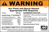
Figure 1
Arc Flash Warning Label
Also
in 2002, the Institute of Electrical and Electronics Engineers (IEEE) issued
IEEE Std 1584 IEEE Guide for Performing Arc-Flash Hazard Calculations. This guide was developed to provide techniques for
determining the arc flash hazard distance and the incident energy to which
employees could be exposed during their work with electrical equipment. Methods
for calculating the incident energy of an arc flash and for establishing the
arc flash boundary in three-phase ac systems are addressed. It also covers the
analysis process from field data collection to final calculated results, provides
the equations necessary to determine incident energy and the arc flash boundary,
and discusses software solutions that can also be used. Also provided is an empirically
derived model for enclosed equipment and open power lines for voltages ranging from
208 V to 15 kV, along with a theoretically derived model applicable for any
voltage. Currently IEEE Std 1584 only addresses three-phase; single-phase ac
systems and dc systems are not included.
The 2004 edition of NFPA 70E was reorganized and
therefore the references to the arc flash hazard analysis changed. Section
110.8(B) Working On or Near Exposed Electrical Conductors or Circuit Parts
that Are or Might Become Energized
(1) Electrical Hazard Analysis (b)
Flash Hazard Analysis provided the direction to
perform the arc flash hazard analysis and referred to Section 130.3 for the
specific requirements for conducting the arc flash hazard analysis. Annex D, Sample
Calculation of Flash Protection Boundary
continued to provide additional information for performing the arc flash hazard
analysis. Annex D also included calculation methods from IEEE Std 1584-2002.
In
addition to the OSHA and NFPA 70E requirements the 2007 edition of ANSI/IEEE
C2, National Electrical Safety Code
(NESC) Section 41 Supply and communications systems – Rules for
Employers, 410 General
requirements, paragraph A.3. requires
the employer to perform an assessment to determine employee exposure to
electric arcs and estimate the incident energy to determine the appropriate
clothing and PPE to be worn by employees. This further emphasized the need to
perform the arc flash hazard analysis.
NFPA
70E-2009 made minor revisions to the requirements which included changing
“Flash Hazard Analysis” to “Arc Flash Hazard Analysis”. One significant
revision was the inclusion of the requirements to consider the design of the
overcurrent protective device and its opening time as well as the condition of
maintenance as part of the arc flash hazard analysis. Paragraph 130.3(C)
Equipment Labeling was added to emphasize the NEC 110.16 requirement to install
a warning label on electrical equipment that specified the available incident
energy or the required level of PPE. Annex D was revised to “Incident Energy
and Flash Protection Boundary Calculation Methods” in order to further emphasis calculation methods for
determining the incident energy and the arc flash boundary.
The 2012 edition of NFPA 70E contains several major
revisions to the arc flash hazard analysis requirements. Section 110.8 in
previous editions was eliminated and the requirements moved to other sections.
As an example 110.8(B) was revised and moved to a new Section 130.3(B) and the
specific requirements for the arc flash hazard analysis were moved to Section
130.5. Section 130.5(C) Equipment Labeling was expanded to identify the types of equipment requiring labeling as
well as specific types of information that is required on the label. One very
important requirement was added to the equipment labeling and is stated in the
last sentence of 130.5(C), which states “The method of calculating and data
to support the information for the label shall be documented.” Whether the incident energy of a potential arc
flash is calculated using Annex D or engineering software programs, or whether
it is determined through use of Table 130.7(C)(15)(a) Hazard/Risk Category
Classifications and Use of Rubber Insulating Gloves and Insulated and
Insulating Hand Tools-Alternating Current Equipment (Formerly Table 130.7(C)(9), the calculation methods
and the data used to determine the information of the warning label must be
documented. This information would include the available short circuit current,
the clearing time of the overcurrent protective device, the working distance of
the employee, and the arc gap. The Hazard/Risk Category Tables cannot be used
at “face value” without verifying the parameters that are noted in each task
group.
Another
significant revision that occurred in the 2012 edition is the inclusion of
direct current (DC) arc flash calculation methods found in Annex D, Section D.8
Direct-Current Incident Energy Calculations and the DC hazard/risk categories found in Table
130.7(C)(15)(b) Hazard/Risk Category Classifications and Use of Rubber
Insulating Gloves and Insulated and Insulating Hand Tools — Direct
Current Equipment.
OSHA issued the Final Rule Federal Register revision
of 29 CFR 1910.269 Electric Power Generation, Transmission, and Distribution, and 1926 Subpart V Electric Power Transmission
and Distribution. One of the
significant revisions is the requirement for the employer to estimate incident
energy of potential arc flash incidents. The following OSHA quotes are provided
for information:
1910.269(l)(8) Protection from flames
and electric arcs.
(i) The employer shall assess the
workplace to identify employees exposed to hazards from flames or from electric
arcs.
(ii) For each employee exposed to hazards
from electric arcs, the employer shall make a reasonable estimate of the
incident heat energy to which the employee would be exposed.
1926.960(g) Protection from flames and electric
arcs.
(1) Hazard assessment. The employer shall assess the workplace to identify
employees exposed to hazards from flames or from electric arcs.
(2) Estimate of available heat energy. For each employee exposed to hazards from electric
arcs, the employer shall make a reasonable estimate of the incident heat energy
to which the employee would be exposed.
The requirements to perform
the arc flash hazard analysis, which is used to determine the incident energy
of a potential arc flash, establish the arc flash boundary, and determine the
required clothing and PPE has been a requirement for many years. These
requirements continue to increase through revisions to NFPA 70E, the NESC, and
OSHA.
Maintenance of overcurrent protective devices
One
of the key components in performing the arc flash hazard analysis is the
clearing time of the protective devices, primarily circuit breakers, protective
relays, and fuses. Fuses, although they are overcurrent protective devices, do
not have operating mechanisms that would require periodic maintenance;
therefore, they will not be addressed. The primary focus is the maintenance
issues associated with circuit breakers and electro-mechanical protective
relays. These devices have mechanical components or operating mechanisms that
require periodic maintenance, testing, cleaning, adjustments, and lubrication
in order to function properly. According to the manufacturer’s specifications
these devices are required to operate and open the device contacts is a
specified amount of time, generally expressed in cycles or fractions of a
second. Where proper maintenance, testing, adjustments, and lubrication are not
performed or are performed improperly, extended clearing times could occur
creating an unintentional time delay that will effect the results of arc flash
hazard or incident energy analysis.
All
maintenance and testing of the electrical protective devices must be
accomplished in accordance with the manufacturer’s instructions. In the
absence of the manufacturer’s instructions, industry consensus standards such
as the NFPA 70B, Recommended Practice for Electrical Equipment Maintenance, and InterNational Electrical Testing Association
(NETA) ANSI/NETA MTS Standard for Maintenance Testing Specifications for
Electrical Power Distribution Equipment and Systems, should be used for guidance on maintenance
frequency, methods, and tests that should be performed on overcurrent
protective devices.
Several
issues concerning proper maintenance and testing of these overcurrent protective
devices, according to the manufacturer’s instructions, will be addressed. Also
addressed will is how protective device maintenance relates to the electrical
arc flash hazard.
Molded-Case
Circuit Breakers -
Generally, maintenance on molded-case circuit breakers is limited to proper
mechanical mounting, electrical connections, and periodic manual operation.
Most lighting, appliance, and power panel circuit breakers have riveted frames
and are not designed to be opened for internal inspection or maintenance. All
other molded-case circuit breakers that are UL approved are factory-sealed to
prevent access to the calibrated elements. An unbroken seal indicates that the
mechanism has not been tampered with and that it should function as specified
by UL. A broken seal generally voids the UL listing and the manufacturers’
warranty of the device. In this case, the integrity of the device would be
questionable. The only exception to this would be a seal being broken by a
manufacturer’s authorized facility.
Molded-case
circuit breakers receive extensive testing and calibration at the
manufacturers’ plants. These tests are performed in accordance with UL 489, Standard
for Safety, Molded-Case Circuit Breakers, Molded-Case Switches and Circuit
Breaker Enclosures. Molded-case
circuit breakers, other than the riveted frame types, are permitted to be
reconditioned and returned to the manufacturer’s original condition. In order to conform to the manufacturer’s original
design, circuit breakers must be reconditioned according to recognized standards. The Professional Electrical Apparatus
Recyclers League (PEARL) companies follow rigid standards to recondition
low-voltage industrial and commercial molded-case circuit breakers. It is
highly recommended that only authorized professionals recondition molded-case
circuit breakers.
Circuit breakers installed in a system are often
forgotten. There is often the attitude that “the lights are on or the machines
are running, so everything is working fine”. The circuit breakers are not
“working fine” it is closed and working properly would not be indicated until
the circuit breaker is required to trip due to an overload or short circuit, or
simply opening the circuit breaker to deenergize the circuit. Even though the circuit
breakers have been sitting in place supplying power to a circuit for years,
there are several things that can go wrong. The circuit breaker can fail to
open due to a burned out trip coil or because the mechanism is frozen due to
dirt, dried lubricant, or corrosion. The overcurrent device can fail due to
inactivity or a burned out electronic component. Many problems can occur when
proper maintenance, inspections, cleaning, and exercising of the circuit
breaker are not performed and the breaker fails to open under fault conditions.
This combination of events can result in fires, damage to equipment or injuries
to personnel.
All too often a circuit breaker fails because the
minimum maintenance (as specified by the manufacturer) was not performed or was
performed improperly. Small things like failing to properly clean and/or
lubricate a circuit breaker can lead to operational failure or complete
destruction due to overheating of the internal components. Common sense, as
well as manufacturers’ literature, must be used when maintaining circuit
breakers. Many manufacturers, as well as NFPA 70B, recommend that if a
molded-case circuit breaker has not been operated, opened or closed, either
manually or by automatic means, within as little as six months time, it should
be removed from service and manually exercised several times. This manual
exercise helps to keep the contacts clean due to their wiping action and
ensures that the operating mechanism moves freely. This exercise however does
not operate the mechanical linkages in the tripping mechanism (Figure 2). The
only way to properly exercise the entire breaker operating and tripping
mechanisms is to remove the breaker from service and test the overcurrent and
short-circuit tripping capabilities. A stiff or sticky mechanism can cause an
unintentional time delay in its operation under fault conditions. This could
dramatically increase the arc flash incident energy level to a value in excess
of the rating of personal protective equipment.
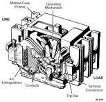
Figure 2
Principle Components of a
Molded-Case Circuit Breaker
Another consideration is addressed by OSHA in 29 CFR
1910.334(b)(2) which states:
“Reclosing circuits after protective device
operation. After a circuit is
deenergized by a circuit protective device, the circuit may NOT be manually
reenergized until it has been determined that the equipment and circuit can be
safely reenergized. The repetitive manual reclosing of circuit breakers or
reenergizing circuits through replaced fuses is prohibited.
NOTE: When it can be determined from the design of the circuit and the
overcurrent devices involved that the automatic operation of a device was
caused by an overload rather than a fault condition, no examination of the
circuit or connected equipment is needed before the circuit is reenergized.”
The safety of the employee manually operating the
circuit breaker is at risk if the short circuit condition still exists when
reclosing the breaker. OSHA no longer allows the past practice of resetting a
circuit breaker one, two, or three times before investigating the cause of the
trip. This previous practice has caused numerous burn injuries that resulted
from the explosion of electrical equipment. Before
resetting a circuit breaker, it, along with the circuit and equipment, must be
tested and inspected by a qualified person to ensure a short circuit condition
does not exist and that it is safe to reset. Any time a circuit breaker has
operated and the reason is unknown, the breaker must be inspected and tested.
Melted arc chutes or interrupters may not extinguish the arc when the breaker
opens under fault current conditions. If the breaker cannot properly interrupt
a second fault, it may fail and may destroy its enclosure and create a hazard
for anyone working near the equipment.
To
further emphasize this point the following quote from the National Equipment
Manufacturer’s Association (NEMA) is provided: (Vince A. Baclawski, Technical
Director, Power Distribution Products, NEMA; published in EC&M magazine,
pp. 10, January 1995)
“After
a high level fault has occurred in equipment that is properly rated and
installed, it is not always clear to investigating electricians what damage has
occurred inside encased equipment. The circuit breaker may well appear
virtually clean while its internal condition is unknown. For such situations,
the NEMA AB4 ‘Guidelines for Inspection and Preventive Maintenance of MCCBs
Used in Commercial and Industrial Applications’ may be of help. Circuit
breakers unsuitable for continued service may be identified by simple
inspection under these guidelines. Testing outlined in the document is another
and more definite step that will help to identify circuit breakers that are not
suitable for continued service.
After the occurrence of a short circuit, it is
important that the cause be investigated and repaired and that the condition of
the installed equipment be investigated. A circuit breaker may require
replacement just as any other switching device, wiring or electrical equipment
in the circuit that has been exposed to a short circuit. Questionable circuit
breakers must be replaced for continued, dependable circuit protection.”
The
condition of the circuit breaker must be known to ensure that it functions
properly and safely before it is put it back into service.
Low-Voltage
Power Circuit Breakers - Low-voltage power circuit breakers are
manufactured under a high degree of quality control, of the best materials
available, and with a high degree of tooling for operational accuracy.
Manufacturer’s tests show these circuit breakers to have durability beyond the
minimum standards requirements. All of these factors give these circuit
breakers a very high reliability rating. However, because of the varying
application conditions and the dependence placed upon them for protection of
electrical systems and equipment, as well as the assurance of service
continuity, inspections and maintenance checks must be made on a regular basis.
Several studies, including IEEE, have shown that low-voltage power circuit
breakers, which were not maintained within a given period of time, have a high
failure rate.
Maintenance
of these breakers will generally consist of keeping them clean and properly
lubricated. The frequency of maintenance will depend to some extent on the
cleanliness of the surrounding area. If there were very much dust, lint,
moisture, or other foreign matter present then more frequent maintenance would
be required.
Manufacturers
of low-voltage power circuit breakers recommend a general inspection, cleaning,
maintenance, testing, adjustments, and lubrication after a specified number of
operations or at least once per year, whichever comes first. Some manufacturers
also recommend this same inspection and maintenance be performed after the
first six months of service regardless of the number of operations. If the
breaker remains open or closed for a long period of time, it is generally recommended
that arrangements be made to open and close the breaker several times in
succession, preferably not under load conditions. Environmental conditions play
a major role in the scheduling of inspections and maintenance. If the initial
inspection indicates that maintenance is not required at that time, the period
may be extended to a more economical point. However, more frequent inspections
and maintenance may be required if severe load conditions exist or if an
inspection reveals heavy accumulations of dirt, moisture, or other foreign
matter that might cause mechanical, insulation, or electrical failure.
Mechanical failure would include an unintentional time delay in the circuit
breakers tripping operation due to dry, dirty or corroded pivot points or by
hardened or sticky lubricant in the moving parts of the operating mechanism.
The manufacturer’s instructions must be followed in order to minimize the risk
of any unintentional time delay.
Figure
3 provides an illustration of the numerous points where lubrication would be
required and where dirt, moisture, corrosion or other foreign matter could
accumulate causing a time delay in, or complete failure of, the circuit breaker
operation.
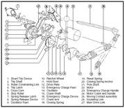
Figure 3
Power-Operated Mechanism of a
Cutler/Hammer “DS” Circuit Breaker
Medium-Voltage
Power Circuit Breakers - Most of the
inspection and maintenance requirements for low-voltage power circuit breakers
also apply to medium-voltage power circuit breakers. Manufacturers recommend
that these breakers be removed from service and inspected at least once per
year. They also state that the number and severity of interruptions may
indicate the need for more frequent inspections and maintenance. Always follow
the manufacturer’s instructions because every breaker is different and the
manufacturer knows what is best for their circuit breakers. Figures 4 and 5
illustrate two types of operating mechanisms for medium-voltage power circuit
breakers. These mechanisms are typical of the types used for air, vacuum, oil,
and SF6 circuit breakers. As can be seen in these figures, there
are many points that would require cleaning and lubrication in order for them to
function properly.
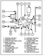
Figure 4
Operating Mechanism
Air Circuit Breaker
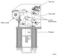
Figure 5
Solenoid-Operated
Mechanism
Arc Flash
Hazard Analysis - As noted at the beginning of this
article OSHA, the NESC, and NFPA 70E require an arc flash hazard or incident
energy analysis be performed before anyone approaches exposed energized electrical
conductors or circuit parts that have not been placed in an electrically safe
work condition. In addition, NFPA 70E requires an arc flash boundary to be
established. All calculations for determining the incident energy of an arc
flash and for establishing an arc flash boundary require the arc clearing time.
This clearing time is derived from the engineering coordination study, which is
based on what the overcurrent protective devices are supposed to do.
Maintenance
is a very critical part of the arc flash hazard issue. The information provided
here clearly indicates the need for a preventive maintenance program on these
circuit protective devices. Evidence has proven that inadequate maintenance
can cause unintentional time delays in the clearing of a short circuit
condition. If, for example, a low-voltage power circuit breaker had not been
operated or maintained for several years and the lubrication had become sticky
or hardened, the circuit breaker could take several additional cycles, seconds,
minutes, or longer to clear a fault condition. The following is a specific
example:
If an arc flash hazard analysis is
performed, based on what the system is supposed to do, let’s say a 5 cycle
clearing time, and there is an unintentional time delay, due to a sticky
mechanism, and the breaker clears in 30 cycles, the worker could be seriously
injured or killed because he/she was under protected.
If the calculation is performed for a
20,000-amp fault, 480 volts, 3-inch arc gap, and the worker is 18 inches from
the arc, with a 5 cycle clearing time for a 3-phase arc in an enclosure; the
results would be approximately 3.5 cal/cm2, which would require arc-rated
clothing and PPE, based on that level of incident energy. The following example
uses the NFPA 70E Annex D equation for a 5 cycle clearing time:
EMB = maximum 20 in. cubic box incident energy, cal/cm2
DB = distance from arc electrodes, inches (for distances
18 in. and greater)
tA = arc duration, seconds
F = short circuit current, kA (for the range of 16 kA to
50 kA)
(1) DA = 18 in.
(2) tA = 0.083 second (5 cycles)
(3) F = 20kA
EMB = 1038.7DB-1.4738tA[0.0093F2-0.3453F+5.9675]
=
1038x0.0141x0.083[0.0093x400-0.3453x20+5.9675]
=
1.4636x[2.7815]
=
3.5 cal/cm2
NFPA 70E, OSHA, and the NESC requires arc-rated
clothing and other PPE to be selected based on this incident energy level
exposure. Therefore the arc-rated clothing and PPE must have an arc rating of at
least 3.5 cal/cm2.
If the clearing time is increased to 30 cycles due to
a sticky mechanism then the results are approximately 20.4 cal/cm2,
which would require arc-rated clothing and PPE based on that level of energy. The
following example uses the NFPA 70E Annex D equation for a 30 cycle clearing
time:
EMB = maximum 20 in. cubic box incident energy, cal/cm2
DB = distance from arc electrodes, inches (for distances
18 in. and greater)
tA = arc duration, seconds
F = short circuit current, kA (for the range of 16 kA to
50 kA)
(1) DA = 18 in.
(2) tA = 0.5 second (30 cycles)
(3) F = 20kA
EMB = 1038.7DB-1.4738tA[0.0093F2-0.3453F+5.9675]
=
1038x0.0141x0.5[0.0093x400-0.3453x20+5.9675]
=
7.3179x[2.7815]
=
20.4 cal/cm2
NFPA 70E, OSHA, and the NESC requires arc-rated
clothing and other PPE to be selected based on this incident energy level
exposure. Therefore the arc-rated clothing and PPE must have an arc rating of
at least 20.4 cal/cm2.
If
the worker is protected based on what the system is supposed to do (0.083
second or 5 cycles – 3.5 cal/cm2) and an unintentional time
delay occurs (0.5 second or 30 cycles – 20.4 cal/cm2), the
worker could be seriously injured or killed because he/she would be under
protected.
As
can be seen, maintenance is extremely important to an electrical safety
program. Maintenance must be performed according to the manufacturer’s
instructions in order to minimize the risk of having an unintentional time
delay in the operation of the overcurrent protective devices.
Summary
With
the proper mixture of training, manufacturers’ literature, and spare parts,
proper maintenance can be performed and power systems kept in a safe, reliable
condition. Circuit breakers, if installed within their ratings and properly
maintained, should operate trouble-free for many years. However, if operated
outside of their ratings or without proper maintenance, catastrophic failure of
the power system, circuit breaker, or switchgear can occur causing not only the
destruction of the equipment but serious injury or even death of employees
working in the area.