Higher Capabilities for Safety-Rated Control Circuits
A truly reliable safety control system must work even when some parts fail. Force-guided relays are unseen components that add another level of reliable operation.
- By Richard Harris
- May 01, 2005
SAFETY interlocks, safety light curtains, and other safety equipment are the visible part of a machinery safeguarding system. As such, they receive the most attention. However, true safety goes well below the surface of any machinery guarding control system. Even when these safety devices work as designed and installed, they must be connected to a control-reliable circuit to complete the job.
Let's look at an example to demonstrate this concept. Using a sensor or interlock to safeguard equipment is a necessary part of any machinery guarding system, but it is only one part of that system. A simple circuit includes a safety interlock switch and a machinery power contactor. Either device can experience a fault, such as a sticking or welded contact. A short circuit also can occur. In each case, the fault renders the safety circuit unsafe, as shown here:
Figure 1. 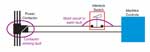
Restructuring the circuit in Figure 2 with redundant machinery power contactors and a double-pole interlock switch increases the probability that the circuit will work, even if a single component should fail. The addition of a safety monitoring relay unit allows users to determine whether the safety circuit is working properly. Reliable safety circuit designs include adding similar layers of redundancy and monitoring to ensure reliable operation as risk factors increase for a given machine.
Figure 2. 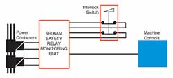
Added Requirements
Applications that require machinery safeguarding circuits that affect more than one circuit simultaneously must include relays with force-guided or positively-driven contacts. The addition of a force-guided relay ensures that when a contact on the relay sticks or is welded, it will not allow other contacts to move.
The concept is similar to a three-phase motor contactor, where all three contacts are mechanically joined so they will move in unison. A force-guided relay employs a rigid mechanical linkage among all contacts to ensure all contacts move in unison. This also ensures they cannot move if any contact sticks or is welded.
The difference, in this case, is that a force-guided relay will have both normally closed (NC) sets of contacts and set of normally open (NO) contacts. A motor contactor has all contacts working with the same function.
Force-guided relays also have a smaller gap tolerance and move more slowly because of design requirements that provide greater precision than a conventional snap-action switch. This comparatively slow-make and slow-break movement makes force-guided relays more prone to contact weld because there is a greater opportunity to cause arcing across the air gap.
Force-guided relays also have a "point of accumulation" closer to the contacts of the relays. This results in slower movement and allows arcing to occur over a longer duration. (See Figure 3.)
Figure 3. 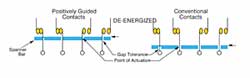
This difference in gap tolerance combines with the "teasing" characteristics of a slower snap action to speed contact wear and material transfer between contacts, and it increases electrical noise or static. When a force-guided relay is used in low-current applications, users should include arc-suppressing devices on the output elements. Any safety monitoring relays or contactors with low current ratings must include arc-suppressing devices in their circuits. Users should consult with the relay manufacturer.
The 'Controller' Configuration
The application of force-guided relays is illustrated in Figure 4. The following sequence of operations forms the basic design for safety monitoring relays and controllers (identified in the rectangle) used on safety light curtains, pressure mats, and other devices requiring safe operation by means of
redundant circuits.
Figure 4 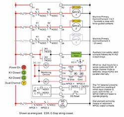
The Machine Primary Control Elements (MPCE) 1 and 2 are typically a relay with force guided contacts. When a safety interlock, light curtain, or e-stop switch opens a circuit, the MPCE NO contacts will open and the NC contacts will close. The relay is wired in this fashion so the MPCE will revert to a safe state in case a power failure occurs.
The use of a force-guided relay ensures that if a welded or sticking contact occurs, it will keep the other set of contacts from moving. The safety-monitoring relay will go into a fault state and not re-energize until someone corrects or fixes the fault at the contact of the affected MPCE.
If a safety control circuit must carry a high current, the outputs from the safety monitoring equipment (light curtain, etc.) must be wired in series (i.e., buffered). The circuit should use a safety-rated relay with positively-driven/force-guided contacts.
False Assumptions
System integrators sometimes incorrectly assume the positively-driven/force-guided relay contacts will operate together and that all contacts, either NO or NC, will remain in the same position. This is not always true.
According to the standard (EN50205) and Comité Européan de Normalisation Électrotechnique (European Committee for Electrotechnical Standardization, or CENELEC) document CLC/BTWG 78-4(SEC) 11:
1) When a NO contact welds, the linkage will prevent the reclosing of NC contacts, and
2) When a NC contact welds, the linkage will prevent the reclosing of NO contacts.
While these conditions will guarantee the required operations listed above on one MPCE, the second MPCE will continue to operate.
Additional Emergency Stop Requirements
As machines become more automated and complex, they will have multiple end effectors that contribute to the hazardous condition in one way or another. Their response must be considered when developing the emergency stop strategy.
Each device or process must become a component of the "safety equation," analyzed and addressed in the final safety circuit design. For instance, it may be necessary to keep cooling pumps or vacuum pumps running, or even to keep them running at higher capacity after the machinery reaches a non-hazardous state. Air-handling fans still may need to run after a safety shutdown to clear hazardous vapors.
An emergency stop system may remove energy only from the end devices causing the hazard. It will not allow the system to restart until that safety device has been reset and the master reset has been activated. Remember that any and all other devices or control circuits and status indicators may be unaffected and remain energized.
This article appeared in the May 2005 issue of Occupational Health & Safety.
This article originally appeared in the May 2005 issue of Occupational Health & Safety.