Air Monitor Calibration, Bump Testing, and Sensor Challenge
These come under the heading of life safety and mission-critical considerations.
 THERE is no better way to ruin a perfectly good day than to make a mistake in the use of your air monitoring instrumentation. Industrial hygienists; military, industrial and public-sector hazmat teams; fire departments; and safety personnel from all sectors routinely make decisions regarding life safety based, in no small part, on data obtained from air monitoring instrumentation.
Lives, security, property, and the environment hang in the balance as we depend upon our air monitoring instruments to tell us whether a particular environment is safe, contaminated, or immediately dangerous to life and health. This paper seeks to examine and make recommendations regarding the practices of calibration, bump testing, and sensor challenge, and it pays particular attention to the quality of the calibration gases used. Recent advances in gas packaging and flow control systems also are discussed.
A wide variety of air monitoring instruments is available with many features, functions, and benefits. We critically need these air monitoring instruments to function properly in the "moment of truth" to accurately detect the contaminant of interest and signal dangerous conditions to the user. Most air monitor users have had monitors and/or sensors malfunction, and generally they have discovered this malfunction during calibration or bump testing. But exactly when did the malfunction occur? Was it a sudden and terminal failure, or was there a subtle, gradual deterioration?
While most malfunctions are discovered at the time of calibration or bump testing, at some point between calibrations the monitor manifested a problem. It is this author's opinion that calibration and bump testing should be performed far more often than once per month. Thus, the objective of this paper is to encourage more frequent air monitoring instrumentation calibration, bump testing, and sensor challenge, as well as to stimulate creation and practice of the proper protocols and utilization of the appropriate grades of calibration gases.
Current Practice
From a protocol preparation and practice perspective, we have a critical need to establish procedures and training that, when followed, will verify that our direct-reading air monitor is actually working properly. OSHA's Safety and Health Information Bulletin (SHIB) 05-04-2004, "Verification Of Calibration for Direct-Reading Portable Gas Monitors," and The International Safety Equipment Association Position Statement "ISEA Position Statement on Verification of Calibration for Direct Reading Portable Gas Monitors Used in Confined Spaces" (dated Nov. 20, 2002) provide excellent protocol preparation guidance. Beyond any shadow of a doubt, strictly following these guidelines, at a minimum, is a wise practice.
Unfortunately, actual in-field practice with gas monitors sometimes diverges significantly from these guidelines. As unpleasant and troubling as the thought might be, air monitors are frequently pulled out of their storage case, "fired up," and put to use minus calibration, functional ("bump testing") test, or even a sensor challenge. To industrial hygienists and environmental, safety, and emergency response professionals, the reasons why this is unacceptable practice are readily apparent and legion.
It is important to begin the discussion by reviewing the prevailing standard terms used in air monitoring. These foundational terms are the clear definitions for calibration and bump testing of portable air monitoring instruments, which ISEA articulated in its position statement and which are cited along with excellent guidance commentary in the OSHA SHIB.
Calibration: the adjustment of an instrument's response to match a desired value compared to a known concentration of test gas.
Bump Testing: functional (bump) testing, a means of verifying by using a known concentration of test gas to demonstrate that an instrument's response to the test gas is within acceptable limits.
To these clear definitions, the author wishes to add and define an additional term: sensor challenge.
Sensor challenge: exposing a monitor's sensor(s) to a concentration of calibration gas, which will cause the monitor's alarms to function.
Monitors' Capabilities & Operation
In order to apply these definitions correctly, it is necessary to examine the capabilities of today's genre of air monitoring instrumentation. Regardless of the type of monitor, during calibration, bump testing, and sensor challenge, the user typically connects a cylinder of calibration gas to a pressure-reducing regulator, which also regulates the flow rate of the gas, and connects this assembly to the instrument by means of hose or tubing, which must be compatible with the gases being measured. Calibration gas is then flowed over the monitor's sensors and a reading is obtained, from which judgments can be made regarding the monitor's accurate operational status.
Whether we are discussing calibration, bump testing, or sensor challenge, it is highly advisable to begin the process(es) by inspecting the monitor, cylinder valve outlet, regulator, and tubing to ensure they are clean; free of moisture, dust, dirt, and debris; and not plugged up. Filters are highly advisable to protect the monitor from these troublesome contaminants.
Many current air monitoring instruments have automatic calibration functions, either integral to the monitor itself or in conjunction with an additional piece of equipment (i.e., a "docking station"). Such instruments' responses are typically not adjustable by the user. During calibration, if the monitor fails to read a value that is within the acceptable limits of error for that monitor, an error message is typically displayed. Some "auto-cal" monitors can become inactive at that point and may have to be sent to a repair facility for further diagnostics and repair.
Some monitors also are equipped with an onboard pumping system that is used to bring sampled air to the sensors from remote locations. Pump-equipped monitors can use a special "demand flow" regulator in order to supply calibration gas to the sensors. Demand flow regulators deliver the calibration gas to the inlet of the pump only when the pump calls or "demands" gas, hence the name "demand flow" regulator. Some pump-equipped monitors can be calibrated or bump tested without the use of a demand flow regulator by using a flow-matching device. These devices, which are dramatically less costly than demand flow regulators, work on the principle of "wasted flow."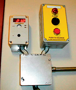
Flow matching devices function very similarly to the old instrument technician's trick of connecting a T in the hose, with one leg connected to the calibration gas regulator, one leg connected to the monitor pump inlet, and one leg connected to a piece of hose that is inserted into a small cup of water. In the old technique, the regulator is turned on, flowing gas into the T, and bubbles are observed in the water. Then the instrument is turned on, and the pump begins to draw gas into the sensors. The flow is adjusted so that a small stream of bubbles is observed leaving the hose outlet under the surface of the water in the cup. At that point, the flow is essentially at atmospheric pressure and matches the inlet demand flow rate of the pump. The drawback with this technique is that if performed incorrectly, you can aspirate water into the monitor, which can cause a host of other problems with the monitor.
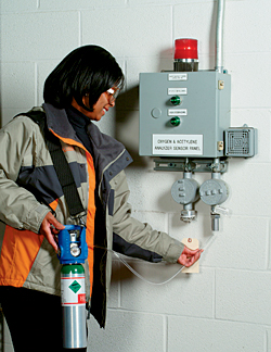
Different designs of flow matching devices can be used with or without a regulator. The photo at the beginning of this article is of a flow matching device that requires no regulator for cylinder pressure up to 1000 psig, as is seen by the C10 connection at its base. In the model depicted in the photo, there is a ball in a transparent flow tube. The flow matching device is connected to the cylinder, and a hose is used to connect the flow matching device to the monitor. The valve is turned on and the knob adjusted so that the ball is suspended at about halfway up the flow tube. Then, the monitor pump is engaged and the flow knob is adjusted to maintain the position of the ball at about halfway up the tube. At this point, the pump is receiving exactly what it is demanding, with a slight excess being vented through the open top of the flow tube.
Another technique exists for providing calibration gas to a pump-equipped monitor without the use of a demand flow regulator. With this technique, the user first determines the pump inlet flow rate, then selects a fixed flow regulator with a flow just slightly higher than the pump inlet flow demand. For example, if the pump inlet flow rate is 0.3 liters per minute, the user would select a fixed flow regulator with a flow of 0.5 liters per minute.
A device with an integrated multiple-setting flowmeter can be used to supply calibration gas at a flow just slightly higher than the pump inlet demand flow rate. After the appropriate flow rate is selected, the gas is simply fed to the monitor, the pump turned on, and the calibration proceeds as normal, subject to any electronic "lock out" functions that might not permit operation of the pump without the manufacturer's "special" set-up (i.e., in certain manufacturers' "docking stations"). Another "down and dirty" technique is to utilize a plastic bag, normally intended for atmospheric "grab samples," from which all air has been squeezed out, filling the bag by delivering calibration gas from a calibration gas cylinder equipped with a fixed flow regulator. The monitor hose is then placed into the bag as carefully as possible to preclude air leaks around the hose/bag interface, and the pump is turned on. The pump will draw calibration gas from the bag at the rate the pump demands.
Note that most monitors with on-board pumps can use these alternative techniques, but there is at least one manufacturer's monitors that may experience damage.
Always consult the monitor manufacturer before attempting to substitute for demand flow regulators.
Other Calibration Issues
The point here is that if you are in the field, have no demand flow regulator, and have an emergency situation for which you need to verify proper air monitor operation and accurate air monitoring, you need to calibrate and/or bump test or at least challenge the sensor. These alternative techniques may be applicable to your monitor, absent a demand flow regulator.
Thus, for any style of monitor, with or without a pump, manual or "auto-cal," when the proper pressure and flow rate of calibration gas is flowing across the sensor, the monitor's reading can be compared to the concentration value shown on the calibration gas cylinder to verify the monitor is accurately sensing and displaying the correct concentration of the gas of interest. This is true for full calibration, functional (bump testing), or sensor challenge, such that the distinction between calibration and bump testing appears to blur a bit, the only difference seemingly being whether there is an adjustment to the sensor readings.
No matter whether you have a manually adjustable or "auto-cal" monitor, you are not finished until you document and retain the calibration data, such as monitor identification number, operator name, calibration date, calibration gas manufacturer, calibration gas concentrations, and some identification tracking for the cylinder, such as a bar code number.
Whether the user's intent is to perform a full calibration, bump test, or sensor challenge, and regardless of the monitor's ability to "auto-cal" or whether it is pump-equipped, it is advisable to use a calibration gas of sufficient concentration to exceed the concentrations at which the monitor displays alarm conditions. Otherwise, there is no verification the monitor is functioning properly in the most important range of its operation, namely when dangerous concentrations of the gas of interest are encountered. Alarm concentrations are the most important of all concentrations at which calibration, bump testing, or sensor challenge is performed, and the concentrations at which you cannot afford errors!
Another critical element to calibration, bump testing, and sensor challenge is setting or reconfirming the zero point of the monitor, termed "zeroing" the monitor. Zeroing is accomplished by introducing a sample of "clean gas," most often air, across the monitor's sensors to verify that when there is "zero" concentration of the gas of interest present, the monitor indicates a reading of zero on the readout. Choice of the zero gas depends on the gas you are monitoring. In any case, the concentration of the gas of interest should be essentially "zero" for this operation.
Frequently the "zeroing" operation is performed in "clean air." But what actually constitutes "clean air"? Generally it is air obtained in a location that is felt to be free of the gas to be monitored, which is then introduced across the monitor's sensors. But because many gases to be monitored cannot be smelled, tasted, or seen, "clean air" taken from a remote location is not generally provably "clean." "Clean air" is a very relative term, unfortunately utilized when great specificity is most advisable.
Some monitors have an "auto-zero" function that zeros the monitor in the ambient air in which the operator is located. Obviously, care needs to be taken that the ambient air is "clean," but another concern is that the operator may think the monitor has performed an "auto-cal" when in reality all that has been done is an "auto-zero."
An example of inaccuracy caused by using an incorrect grade of calibration gas (i.e., not a certified grade) can be seen when using an "air" calibration gas to calibrate oxygen sensors. With "air," the oxygen concentration can vary, especially if the gas manufacturer uses synthetic air. Synthetic air is manufactured by blending oxygen and nitrogen. Most gas manufacturers, in order to maintain the extremely low concentration of hydrocarbons needed for "zero air," use extremely pure oxygen and blend it with equally pure nitrogen to make "zero air." It is risky to assume that "air" or "zero air" contains exactly 20.9 percent oxygen. Depending on the gas manufacturer's procedures and product specifications, with synthetic air, actual oxygen concentration can range from 19.8 percent to 21.9 percent because of errors inherent to the gas manufacturing process.
The photo at right shows a stationary oxygen monitor that has been calibrated with a "zero air" mixture, possibly certified as to hydrocarbon concentration but not certified as to oxygen concentration, and assumed to contain 20.9 percent oxygen in nitrogen. The preparation error inherent to the gas manufacturer's process has obviously yielded a calibration gas in which the oxygen concentration was lower than 20.9 percent. Thus, when the monitor samples ambient air, the concentration sensed is incorrectly displayed as 21.2 percent. Likewise, calibrating using an "air" calibration gas that contains 19.8 percent oxygen but is assumed to contain 20.9 percent oxygen can cause the monitor to not signal danger when ambient oxygen concentrations fall below 19.5 percent--until the ambient oxygen concentration becomes seriously low (i.e., below the OSHA limit of 19.5 percent oxygen as established in 29 CFR 1915.12(a)(2)). Unless the use of a non-certified oxygen concentration calibration gas has been specifically approved by the instrument manufacturer, to ensure maximum accuracy, oxygen sensor calibration requires a calibration gas for which the oxygen concentration has been certified. This is especially important when the instrument operator manually adjusts the instrument response to correspond with the concentration of oxygen shown on the calibration gas cylinder or that has been assumed to be in the cylinder.
An issue that arises on occasion involves cross interferences of certain gases because the sensor sometimes can confuse one gas for another with varying levels of sensitivity. This cross sensitivity can be a real problem in an environment where background gases exist on a regular basis.
Recommended Practices
For these reasons, this author recommends the use of a certified "zero" grade gas, usually air or nitrogen, that is certified to be essentially free of the gas to be monitored. Considering the life safety and mission-critical role of air monitoring, air monitor users should, well in advance of actual monitor use, prepare a written protocol governing (1) monitor calibration and use, (2) selection of calibration gas for monitors, and (3) training and practice of the protocol for the personnel within their purview. The protocol should follow the guidelines of ISEA and OSHA, at a minimum. Every single time an air monitor is turned on, especially if the purpose is to obtain data regarding the safety of a particular environment, that monitor should be calibrated, bump tested, or at the absolute least have the sensors challenged by exposing them to a concentration of the gas of interest that will cause the monitor's alarms to function.
Failure to follow this recommendation may result in a lack of verification that the monitor is operating properly and may result in false confidence in the monitor's ability to accurately detect and signal dangerous concentrations of the gas of interest to the operator. If you cannot calibrate, bump. If you cannot bump, then challenge the sensors/alarms. In all cases, zero the monitor with a certified zero gas.
Additionally, it is advisable to verify that the monitor is still operating properly during long periods of use. The individual responsible for preparing the air monitor use protocol should pay particular attention to whether the monitor will be used for many continuous hours and should determine and specify in the use protocol the maximum length of continuous operation time before recalibration, bump testing, or sensor challenge should be performed. This author believes several hours of continuous operation should trigger a recalibration, bump test, or sensor challenge, as should any unusual event experienced with the monitor. Examples of unusual events are dropping the monitor, encountering significant concentrations of the gas(es) of interest, encountering significant concentrations of another gas or contaminant, battery failure or exhaustion, exposure to high levels of moisture such as being gross-decontaminated at a hazmat scene, and being left on in operating mode unattended.
In all cases, be sure the documentation is performed and preserved. As pointed out by Joe Spratley in his article "Are Your Gas Monitors Just Expensive Paperweights?" (Industrial Hygiene News, Vol. 28, No. 5, July 2005, pp. 16-17, Rimbach Publishing, Pittsburgh, Pa.), calibration data stickers attached to the monitor are also an excellent practice and should be part of any monitor calibration documentation protocol.
Selection of monitors and calibration gas equipment and preparation of the use protocols should always be done with these myriad and critical factors in mind. At the same time, ergonomics and user-friendliness must also be considered if we are to foster compliance with the established protocols and pertinent guidance documents in order to achieve our prime mission objective, which is always life safety.
This article appeared in the October 2006 issue of Occupational Health & Safety.
This article originally appeared in the October 2006 issue of Occupational Health & Safety.