The Value of Thermography Windows
Infrared imaging technology helps to improve electricians' on-the-job safety.
- By Leah Friberg
- Oct 01, 2010
Shock, electrocution, arc flashes, and arc blasts are responsible for one fatality every workday in the United States, and some 8,000 workers are treated in hospital emergency rooms for electrical contact injuries each year.
The goal of any electrician or other technician using thermal imagers is to prevent unplanned shutdowns in a manner that is reliable, repeatable, and, above all, safe. Because they work with the target equipment both online and on-load, often using infrared (IR) cameras that cannot "see" through panel covers, thermographers (electricians and other technicians who use modern thermal imaging tools) face severe safety hazards -- even electrocution -- when attempting to scan electrical distribution equipment.
 Yet most electrical accidents are not the result of direct electric shocks. Shorting faults occur when the insulation or air separation between high-voltage conductors is compromised.
Under these conditions, a plasma arc -- or "arc flash" -- may form between the conductors, unleashing a potentially explosive release of thermal energy. Such a flash can result in considerable damage to equipment and serious injuries to nearby personnel.
Short Circuits and Arc Flashes
An electrical system can be subject to two types of shorting faults: bolted faults and arc faults. A bolted fault is everyone's idea of a short circuit: an energized circuit with a ground set in place. A bolted fault results in a very high current; it is a low-impedance short because of the solid connection. Bolted faults behave predictably, so conductors can be rated to withstand the overcurrent for the time required for an interrupt device to kick in. Thus, bolted faults rarely result in an explosion.
The second, and far more destructive, type is the arc fault. This occurs when the insulation (more specifically, the air separation) between electrical conductors is no longer sufficient to withstand their potential difference. This can occur for many reasons. A dropped tool or any other conductive element, even rust, introduced between or near energized components may compromise the insulating clearances. Often, incidents occur when a worker fails to ensure equipment has been properly de-energized. Incidents even can occur when a worker is simply removing a cover from a piece of equipment to inspect it. A significant proportion of arc faults occur simply because of some form of component failure not even involving human interaction.
In contrast to the low impedance required for a bolted fault, an arc fault is a high-impedance short because the discharge occurs through air. The current flow is therefore "comparatively" low. But the explosive effects are much more destructive and potentially lethal. Unlike bolted faults, arc faults are unpredictable. It is difficult to predict exactly how much energy will be released and, in particular, the duration of the fault because this depends on many factors, feedback mechanisms, and the response of the overcurrent protection devices.
Incidence of Arc Faults
NIOSH has published the results of a survey of electrical accidents reported by the Mine Safety and Health Administration in the mining sector during the period 1990 to 2001. In more than two-thirds of the cases of arc flash injuries, the victim was performing some form of electrical work, such as troubleshooting and repair. More surprisingly, 19 percent of the accidents arose from the direct failure of equipment during normal operation. Overall, 34 percent involved some form of component failure.
The threat to personal and equipment safety that arc faults pose means that taking measurements with a cover removed is not a safe option. A better alternative is the provision of a permanent "access point" in the equipment housing.
Ports, Panes, and Windows
Infrared thermography itself is one way to reduce exposure to potential arc faults -- making a non-contact thermal measurement in many cases saves having to make a direct-contact measurement, where the chances of a mistake are higher. But the thermal imager can't see through the panel door, and the minute the panel is open, the technician faces arc fault risk.
For that reason, many facilities are installing IR ports, panes, or windows into panel doors. All three enable thermographers to inspect live electrical equipment through the closed door, but the three options represent different degrees of protection.
An IR port is simply a hole or series of holes; an IR pane is a polymer optic. Both successfully limit physical access (human contact) to live equipment. However, in the event of an arc fault, neither option provides a protective barrier between the thermographer and the exposed conductor and arc flash source. A pane affords little protection because it is a thin polymer with a low melting point.
An arc-resistant infrared window provides a solid barrier between the thermographer and the live conductors in the event of an arc flash resulting from unexpected component failures or work on other parts of the system. Thus, it is possible not only to reduce the trigger effects of an arc, but also to provide the technician with a far safer working environment.
The additional protection afforded by the IR window comes from its crystal optic construction, which is designed to better protect technicians under arc-flash conditions. IR windows can substantially reduce hazard ratings and also help minimize the need for excessively bulky and cumbersome personal protective equipment (PPE).
Thermography windows are a relatively new technology, so there is no specific standard that relates to their construction and testing. However, because they are invariably installed close to arc flash hazards, it is important that windows can withstand not only an arc flash incident but also the rigors of their environment and normal day-to-day operation.
Required PPE
In 2009, the NFPA 70E Standard for Electrical Safety in the Workplace was updated to recognize new hazards, address other safety gaps, and improve protection for electrical workers while helping companies comply with OSHA standards. The standard defines the safety requirements for personnel working on electrical equipment. To comply, employers must carry out a hazard risk assessment and ensure all employees working in a potential arc flash hazard zone use appropriate equipment and wear the right protective clothing.
Among other things, the guidelines recommend a thorough arc flash hazard analysis (see sidebar) to establish the nature and magnitude of the hazard, calculate the shock and flash protection boundaries, and identify the appropriate protective clothing and PPE required for live work. While NFPA 70E covers the PPE requirements for arc flash protection, there are also other considerations and standards to include in any safety appraisal. Workers may require eye protection, insulating gloves, ear and hearing protection, head impact protection, and reinforced footwear.
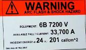
Warning Signs
Although the standard's basic requirement is for a sign warning of the arc flash hazard, it is more helpful for engineers if the sign includes other information, such as:
- Operational voltage
- Fault current
- Flash hazard boundary
- Incident energy at the normal working distance for the arc fault hazard
It is good working practice to make labeling clear and accurate; too much information is as bad as too little. If a system has several access points and arc flash hazards, the signage should indicate the parameters for the greatest hazard.
With the adoption of NFPA 70E and the industry's focus on arc flash safety, reducing the risk of arc flash should be a primary concern for any technician working in a live electrical environment. Contractors, risk managers, and engineers, along with apartment, commercial, and retail building managers and owners, all have a stake in ending electrical-related accidents, liability, and loss. IR windows and increasing observance of the updated NFPA 70E standard should prove to be valuable resources for achieving that goal.
This article originally appeared in the October 2010 issue of Occupational Health & Safety.