
Using Permanent Electrical Safety Devices
Electrical safety radically improves when workers can determine a zero electrical energy state without any voltage exposure to themselves.
- By Philip B. Allen
- Jan 01, 2012
All safety -- especially electrical safety -- is personal to employees. Little else matters to them unless electrically safe work conditions can be created and maintained through their work environment. Article 120.1 of the NFPA 70E was written with the important purpose of establishing the "gold standard" for creating an electrically safe work condition. Since then, however, innovation in the realm of electrical safety has surpassed the precise language of Article 120.1, because it fails to speak directly to the value that permanent electrical safety devices (PESDs) have in achieving an electrically safe work environment. A relatively new concept, PESDs improve workers’ ability to safely isolate electrical energy beyond what was originally conceived when Article 120 was written.
The forward-thinking concept of PESDs goes beyond the high standard of safety for which competent companies strive, yet it still adheres to the core principles found in Article 120.1. With PESDs incorporated into safety procedures, installed correctly into electrical enclosures, and validated before and after each use, workers can transition the once-risky endeavor of verifying voltage into a less precarious undertaking that never exposes them to voltage. Let’s face it, every electrical incident has one required ingredient: voltage. Electrical safety is radically improved by eliminating exposure to voltage while still validating zero energy from outside the panel.
In recent years, PESDs have become a way for Fortune 500 companies to increase safety and productivity simultaneously. Weyerhaeuser started using voltage indicators (a PESD) in 2004, and that quickly spread to other facilities. Warren Hopper, Manufacturing Services manager for Weyerhaeuser, stated, "Use of the fixed voltage indicators would allow us to avoid opening starter or disconnect compartment doors for approximately three-quarters of all lockouts."
Validating a Voltage Detector
An electrically safe work condition requires 100 percent accuracy from voltage detectors. To help ensure this, NFPA 70E 120.1(5) says, "Before and after each test, determine that the voltage detector is operating satisfactorily." Validation means that electricians first check their voltage detector to an independent voltage source (i.e., a nearby 120VAC outlet). Next, they check for zero voltage on the primary source. Work begins only after the voltage detector is rechecked to the independent live voltage source.
This straightforward validation procedure works for a portable voltage detector because it can be physically moved between two voltage sources. Because of this, perhaps the authors of NFPA 70E considered only portable voltage detectors (voltmeters), not PESDs, when writing Article 120.1?
The same principles absolutely apply to PESDs. However, because a PESD cannot be moved between two voltage sources, the technique for validation needs a slightly different approach. Testing for voltage simply requires a small amount of current to flow between the two voltage potentials. The voltage detector circuit determines a voltage potential by relating this current flow to actual voltage and providing the worker an appropriate indication (audible, visual, or digital display).
Validating a Voltage Portal and NCVD Combination
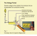 A non-contact voltage detector (NCVD) determines whether or not voltage exists in a conductor by creating a low current capacitive circuit between the conductor, the NCVD, the worker, and ground. Therefore, when the NCVD is positioned close to a live conductor, this completed circuit causes the NCVD to beep or flash, telling the worker that voltage exists in the conductor.
Because voltage portals mount permanently to the outside of enclosures, the worker has to stand in the same place when using his NCVD. This makes this capacitive circuit more reliable and more repeatable than it would be when workers use a NCVD in all other applications. Because NCVDs are portable, they can be checked to an independent voltage source as per NFPA 70E 120.1(5).
Validating a Voltage Indicator
A voltage indicator is hardwired to the three-phase disconnect and earth ground. The circuit illuminates LEDs when AC/DC voltage exists between any two phase(s) and/or ground. Because voltages above 50 volts are deemed unsafe by NFPA 70E, it is imperative that the LEDs on a voltage indicator illuminate for all voltages above 50 volts. Perhaps the most compelling characteristic of a voltage indicator is the wide operating characteristics (40-750AC/30-1000VDC); this feature separates it from other devices, such as a pilot light that quickly would fail if the voltage exceeded its normal operating range (120VAC, +/-10 percent).
A hardwired voltage indicator brings up two interesting issues. First, it is impractical to verify the voltage indicator to another independent voltage source. Trying to accomplish this by adding a switch to toggle between the line voltage and the test voltage adds more components and complexity and leads to unreliability. (This is impractical because it requires a 600V fused three-pole double throw relay. The fusing, the relay wiring, and switching introduces 18 connections -- failure points -- between the voltage source and the voltage indicator.) Second, because the voltage indicator’s sole purpose is to indicate voltage, anything installed between the source voltage and the voltage indicator increases the chance of a false negative voltage reading, including switches, relays, and fuses. Third, because of the three-phase circuit design, a voltage indicator accommodates multiple current paths between phase(s) and ground, thereby reducing the number of possible failure modes. In one possible circuit design, before a single LED illuminates, the current must pass through at least four LED flashing circuits. “Voltage when illuminated” means if only one of the four LEDs illuminates, it still provides voltage indication to the worker.
Multi-meters Compared to PESDs
Creating electrically safe work conditions relied solely upon the portable multi-meter before PESDs came along. This tool is not only used in electrical safety, but also has features making it invaluable for purposes such as electrical troubleshooting and diagnostics. Additionally, a PESD leaves no question or confusion when a worker uses it in creating an electrically safe work condition because it was designed, built, and installed for a single purpose: voltage indication for electrical safety. Understanding these differences helps determine an acceptable validation procedure for PESDs.
Voltage indicators and voltage portals have unique strengths and complementary characteristics, and they meet the validation requirements of NFPA 70E 120.1 when used together. The traditional method of validating the voltage detector to an independent voltage source is met with the NCVD/voltage portal combination. On the other hand, it can be argued that a voltage indicator by itself cannot be validated by the traditional method. However, because permanently mounted voltage detectors are designed only to detect voltage, the built-in advantages over a simple multi-meter needs to be considered in validating this device.
A PESD becomes a real safety device only after it is included as part of a written LOTO procedure. Without this, it is nothing more than another electrical component. The LOTO procedure must explain to the worker each step that involves the PESD. At a minimum, workers will need to verify proper operation of the PESD before and after performing a LOTO procedure.
Mechanical maintenance workers receive a huge benefit when these devices are used in mechanical LOTO procedures. Workers performing mechanical LOTO procedures (work involving no contact with conductors or circuit parts) still must isolate electrical energy. PESDs provide a means of checking voltage inside an electrical panel without exposure to that same voltage. Without these devices, a mechanic performing mechanical LOTO would be required to work in tandem with an electrician using a voltmeter to physically verify zero voltage inside an electrical panel before work begins. In this case, the electrician is exposed to voltage. With PESDs, the mechanic can single-handedly check for zero electrical energy without any exposure to voltage, thereby making the LOTO procedure safer and more productive.
For exactly this reason, a western Pennsylvania power plant increased both the safety and efficiency of its operators. Operators were able to perform more maintenance tasks during off-shift hours by installing voltage portals into each motor control center bucket, rewriting their LOTO procedure, and training the operators to use NCVD detectors with voltage portals. In the past, even a simple maintenance task such as replacing a broken fan belt was side-barred until the first-shift electrician arrived to lock out the electrical energy feeding the fan motor. In the end, both electricians and operators became more productive and still complied with OSHA LOTO requirements.
Reduced Arc Flash Risk and PPE
Electrical safety improves when workers can determine a zero electrical energy state without any voltage exposure to themselves. Verifying the proper operation of a meter and testing for absence of voltage before working on electrical conductors (testbefore-touch) must remain a habitual practice for workers. The goal of PESDs is to ensure when workers test-beforetouch, they test only dead conductors.
Therefore, after completing a hazard risk analysis (NFPA70E Annex F) on the installation and PESDs written into this procedure, users may conclude this task may be done without special PPE. Without PESDs, a failure of an isolator may go undetected until the electrician discovers live voltage after opening the panel. This exact scenario is a common cause of arc flash. A direct short circuit may result from one misstep by the electrician while checking voltage. Worse yet, the electrician would take a direct hit in the face from the resulting arc flash. Because PESDs meet NFPA 70E 120.1 and there is less risk of voltage exposure, some will conclude that the need for personal protection equipment is reduced once the panel is open. Whether or not you agree with this, voltage detectors are a low-cost, redundant voltage verification tool that reduces arc flash risk, increases safety, and adds productivity for an installed cost of $150.
Safety evolves based on best work practices and innovation. High safety standards not only create safer workplaces, but also encourage safety innovations. Now, thinking outside the panel doesn't leave you boxed in.
This article originally appeared in the January 2012 issue of Occupational Health & Safety.